

When designing aluminum castings, you must take into account their application, appearance, performance, precision, and the significant cost. You need to determine the purpose of the part and balance your requirements to meet the budget. Here, we have highlighted the main matters that should be considered when designing the part.


Home / Aluminum Die Casting Design Guide
Aluminum Die Casting Design Guide
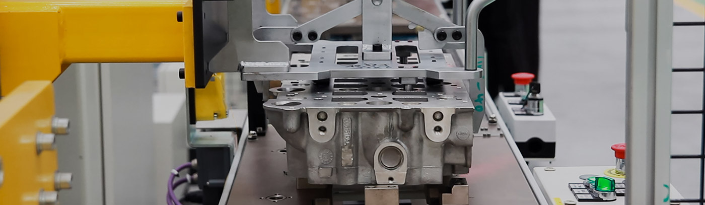
The correct design method can significantly enhance your manufacturing experience. If you are involved in the die-casting industry or want to improve your knowledge of die-casting design, then this Aluminum Die-Casting Design Guide is exactly what you need. Mechanical engineers and product designers will find this design guide very useful. We have focused on introducing some important design factors and limitations, which can significantly simplify the aluminum die-casting process and thereby reduce production costs.
We offer a one-stop aluminum die-casting manufacturing service. Our engineers will carefully inspect every product we produce to ensure that each component is suitable for mass production. If you have any questions or concerns about the aluminum die-casting project, please feel free to contact us at any time.
Design Requirements
Munus usura
Cum designans aliquod opus, eius potentiae applicationes considerari oportet. Aluminium partes mori-castriae non solum functionibus structuralibus inservire possunt, sed etiam aesthetica augere. Ergo popularis alternatio facta est ad alias materias.
Ob hoc quod moderni computatores multo potentiores sunt quam ante, processui temporis pluries auctus est. Partes pressae non solum praestantissimum momentum structurae habent, sed etiam munera aesthetica praeclara possident.
Perspicue designare propositum partis machinae emissae. Hoc adiuvare potest materiam aptam eligere et aptam tolerantiam determinare pro consilio parametris in tuis requisitis fundatis. Considerare etiam debes corrosionis resistentiam, vires ad pondus, rationem, conductionem, aliasque partis partis proprietates.
Quamquam clientes saepe finem reddendi pro qualitate et viribus suis requisita longe excedunt. Ideo plene cognoscens usum partium functionis iuvabit te processum morientium mittentes melius comprehendere.
Aspectus Requisita
Pro aluminis internis dejectiones, species non magni momenti est. Sed in exterioribus conjecturis, ut puta conchis aut insterni, fit species magni ponderis.
Fines usores semper anteponunt pro effectibus aesthetically placentes. Et ideo, pro parte operis, sumitur exa- plum. Hinc externae partes iactae carum speciem habere debent.
Cum igitur partes designando, ratio aesthetica habenda est rationi. In antecessum curationis superficiei effectum consequi cupis. Curatio superficiei bonae tutelae contra extremam tempestatum condicionem additional providere potest.
Conventus Methodus
Processus conventus aluminii dejectiones relative simplex vel valde implicata esse potest, secundum partium multiplicitatem. Traditional iactatio instrumentorum certas limitationes in speciebus partium quae eici possunt. Ergo ante difficile erat singula intricata mittere.
Partes autem complexae dividi possunt in aptas sectiones et tunc conexae per methodos convenientes congregationis post rejectionem. Communia quaedam artificia in conventu mori-mittentes comprehendunt:
- haerens
- Thread
- Welding
- Iniectio components metallum efficta
- EXERCITATIO Cori juvenum, etc.
Priusquam a consilio incipias, certas conventus technicas eligas oportet pro partibus emortuis. Cum methodus conventus modum consilio signanter afficere potest, elige opportunum conventum optionem convenientem quae requisita tua occurret.^
Donec pretium
Propositum analysin analysin analysi accuratam gerere debes. Quia proventus budget directe afficit omnem rationem negotii tui faciens. Consilium tuum innitendum est in praevisione ad requisita budget.
Designatores periti signanter sumptus mori mittentes sine ullo partium qualitate minuere possunt. Certis parametris consilio inhaerere debes ne partes nimis designans et sic sumptus supervacuos vitare debeas.
Exempli gratia: striatus additus efficit ut partes leviores designes sine sacrificio effectus. Potest etiam materialia gratuita minuere. Praeterea reducere vel eliminare chamfers et angulos aculeos signanter summittere possunt sumptus et multiplicitatem formarum et processus emittentes.
Product Structure Design
Proper design of aluminum die-cast parts faces numerous challenges. Even the smallest features in the design can have a significant impact on the casting process. Therefore, every detail should be carefully designed in accordance with the recommended guidelines.
We have focused on introducing the main features of aluminum die-casting design. You will find recommended precision for many important features and understand the design considerations that should be followed during the product design process.
Materia Electio
Productum consilium signanter secundum electionem materiae variari potest. Quisque stannum certos habet limites. Ad optimam integritatem et robur aluminii flatura moriendum, diligenti consilio et execu- tione opus est.
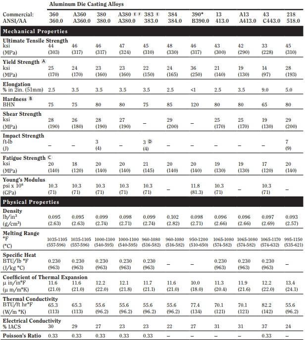
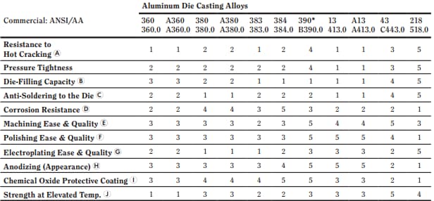
Secundum compositionem elementorum mixturae in aluminio adhibitae, eius pondus, fluiditas, vires, conductivity, punctum liquescens et aliae proprietates variari possunt. Sed non mixtura elementorum ad materias ejiciendas apta sunt.
Aluminium populare quaedam mixturas quae adhiberi possunt ad moriendum includunt:
- A380
- A383 (ADC12)
- A413
Multa alia genera aluminii mixturae praesto sunt. Oportet eligere unum secundum necessitates tuas et necessitates oeconomicas.
Draft
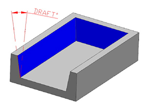
Angulus captura est unus e maximis parametris in aluminium dejectus. Indicat gradum cerei seu inclinationis inter nucleum et superficiem partis et lineae formse. Nos etiam angulum latrinam appellamus.
Excogitatoris sufficientem eiectionem angulos cum necesse est praebere debet. Quia sine adaequata eiectione anguli, dejectiones difficile erit post concretionem removere, et adhuc possibilitas laedendi partes vel etiam forma ipsa.
Design Considerations of Draft
Cum calculandum angulum digredientem requisita, sequentes factores in rationem sume:
- Fere angulus communis chamfer pro plurimis geometricis rationibus adoptatur.
- Sunt aliquae exceptiones pro muris interioribus et superficiebus. In quibus bis plerumque exterioris parietum volumen evacuatio est.
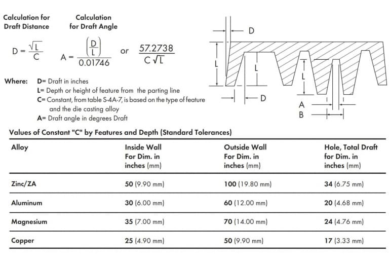
- Requisita typorum typorum variari possunt secundum mixturae usus ad proiciendum. Calculari debes angulum capturam secundum genus aluminii mixturae quam elegeris.
Sequentia illustrabunt vexillum tolerantiae superficiei internae ad angulos capaces aluminii dejectiones diversarum profunditatum.
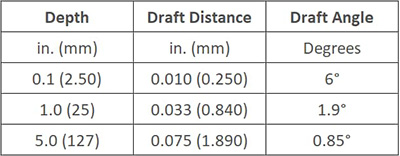
Vexillum tolerantiae ad quodlibet offensionis sequenti aequatione computari potest.
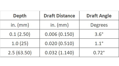
Si minorem capturam angulum consequi vis, tolerantias accuratas uti potes. Nihilominus, hoc accuratius processui requirit ac superiora gratuita incurrit. Ideo commendatur ad vitandas tolerantias accuratas, nisi sit omnino necessaria.
Accurate tolerantiae superficiei internae pro captura aluminii dejectiones diversarum profunditatum sunt hae.
Haec est formula accurate computandi tolerantiam partium.
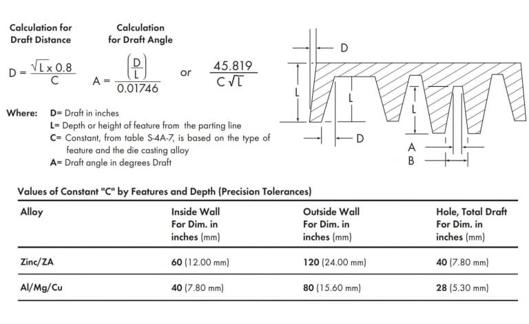
Quaeso note quod schema supra captura ad notionem conceptus melius auctum est. Re quidem vera schematis schema perparvum est et, nisi diligenter observatur, omnino impossibile est observare.
Movere Die & Fixum Die
Forma ordinata et figuratio fixi motus vitalis est momenti. Etiam si unus ex eis repugnet, aluminium impediet processus iaciens mori. Consilium movens forma plerumque provocatio est. Structura formae fixae relative simplex est, sed forma movens plura elementa tractare debet. Cum materia in fomacem injecta est, propter nimiam pressionem materiae, nucleus elabi potest, inde in dimensionibus oversized.
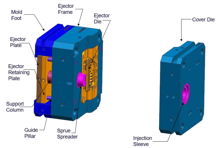
Tolerantiae formae moventis componentes ab lineari tolerantia et proiectione in area tolerantiae pendent. Inter eos, linearis tolerantia ad longitudinem lapsus nuclei formse refertur, dum proiectio ad caput lapsus spectat ad nucleum formae fusilis contra materiam.
Motus perfici potest per directionem linearem perpendicularem in area proiectionis. Optimum est ergo servare tolerantiam ad movendum formas componentes ad minimum valorem nullius gradus.
Ob structuram instrumentorum iactorum, tantum relative magnae vel positivae tolerantiae in productione processu permitti possunt. Ex quibusdam variabilibus area projecta, vexillum tolerantiae et tolerantiae praecisio haec sunt. NADCA indices.
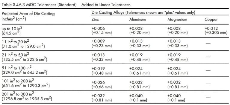
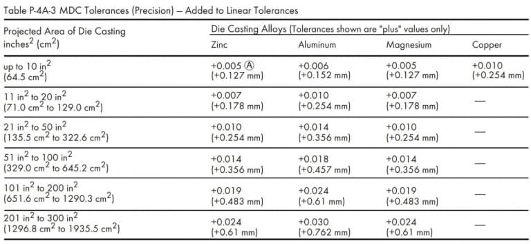
Discedens linea
Distinctio linea est locus ubi duae medietates formae confluunt ad plenam producti structuram formandam. Ob processum emissionis missum, formatio lineae partitionis inevitabilis est. Consilium enim semper includit duo ad minus.
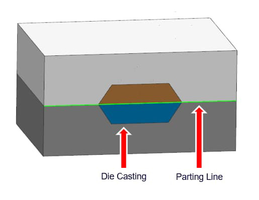
Distinctio lineae clare significat distinctionem inter mori mobilem et formam fixam mori. Recta tolerantia divortia ad maximam quantitatem separationis formse refert, quae permissa est ut proprium aluminii processum morientium executionem curare permittatur.
Cum pressio materialis duas partes formae ad separandum cogere conatur, materia ab puncto separato per lineam divortium effluet. Hic est fulgor vitiorum in mori mittentes. Dejectio additos processus perfectionis requirit ut fulgura, risores, portas et portus exundantia removeant. 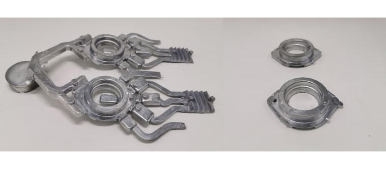 Recta tolerantia discidium est functio areae formae proiectae, quae repraesentat superficiem separationis, ubi materia fusilis ab uno dimidiato in alterum movetur.
Formae omnino clausae nullos inter se hiatus habent, itaque tolerantia area projecti semper affirmativa est. Gradus separationis formse pendet a testa pressionis formae et vi clamping applicata ad binas partes formae clausae.
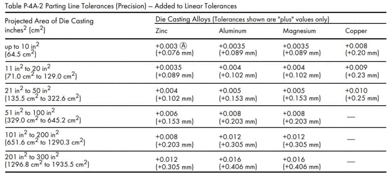
Recta tolerantia in angore, magnitudine et profunditate partis diversae discurrentes variabunt. Commendatae normae tolerantiae valores et valores tolerantiae praecisiones ad lineam emissam intereuntis sunt hae.
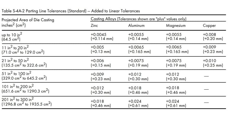
Attamen, si area proiectae partis iactus aleatoria superat trecentos digitos quadratos, officinam emissationem (1935.5 cm²). consule, quaeso.
Machining Allocacio
Machinae cibaria ad quantitatem materiae rudis quae ex aluminio perfecto emissae partis emortui removeri possunt. Dejectiones habere asperitatem superficiei et figuras geometricae, quae leviter a consilio ipso deflectunt. Ergo, post mortem dejectionem, requiritur processus secundarius ad hos errores corrigendos. 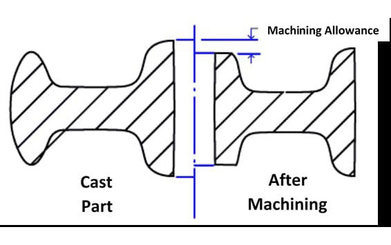
Clavis est ut optimae proprietates mechanicae et densitas eiectamentorum in superficie vel circa superficiem sita sint. Itaque de machinis prebenda diligenter determinatur ad partes minus densas penetrandas.
Attamen, in scenis designandis, certa machinæ cibaria certa quantitate machinæ et variabilium ejiciendi debent. Si apparatus opportunus nimis exiguus est, potest non occurrere in qualitate superficiei requisita, et periculum est defectus in partibus relinquendi.
Ex altera parte, nimia machinis prebenda partium augebit tempus productionis, laboris impensas et altiore expensas. Consultatio cum victu in antecessum morientes adiuvabit ut congruam machinis prebendam determinet.
Fere, minimi machinæ prebenda debet esse 0.010 digitorum (0.25 millimetrarum) ut instrumentum vestium minuat et porositatem fusurarum minuat. Maxima prebenda machinæ summa est minimae prebendae machinæ ac dejectionum deformatio.
Hoc est exemplum comparationis machinis auxit in duobus diversis respectibus positionum.
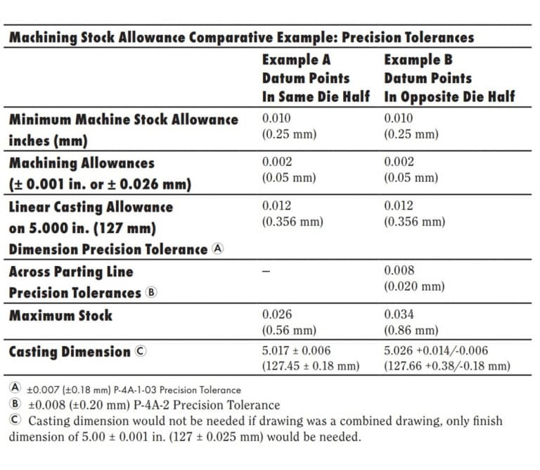 Sed in planis et magnis partibus aliqua consideratio superaddita est. Conservare potes cum triae prebenda valores machining hoc in casu.
Murus Crassitudo
Semper nituntur servare parietis crassitudinem totius componentis uniformem. Crassitudo uniformis prodest melioribus fluxu et solidificatione metallica. Ergo melior erit qualitas et integritas iectionis.
Sed si muris variabiles crassitudines in consilio tuo praebere debes, in modum angulis rotundatis/radii gradatim transitum inducere debes pro crassitudine abrupte mutans. Alioqui acutae acutae in tuo consilio manebunt.
In product design, acutas oras nullas esse. Hoc est, quia hoc metallum afficiet fluxum et formam eiectis difficulter removere. Attamen, si parieti in bivio congrediuntur, hae acies retineri possunt.
Commendatur Wall Crassitudo
Quanquam enim parietis crassitiem aut tenuitatem nullum omnino signum est, optimum est eum intra certum modum continere. Crassitudo muri typica extensio pro aluminio iacturae moriuntur est 0.0787 digitorum (2.0 millimeters) ad 0.1378 pollices (3.5 millimeters). Hoc etiam pendet a partium magnitudine ac structura.
Hoc tamen variari potest secundum mixturam dejectionis, figurationis partis, magnitudinis partis, et applicationis. Exempli gratia, si magnitudo partis parva est, sectionem parietis tam tenuissimam pollices quam 0.020 mittere potest (0.50 millimeters).
Excipere tamen possunt ad crassitudinem parietis maximam et minimam tam parvae quam magnae aluminii dejectiones. Si quas quaestiones occurrant, officinam iectionis consulere potes.
Vitare densissima ac tenuis Wall
Muri crassitudo auget rigorem partis. Sed murus nimis crassus processus refrigerationem morabitur, processus solidificationis impediens. Ergo, nisi congrui mensurae sumantur, fiet in vilitate abjectionis.
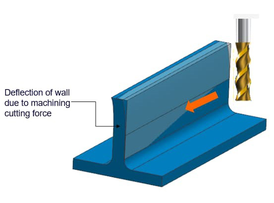
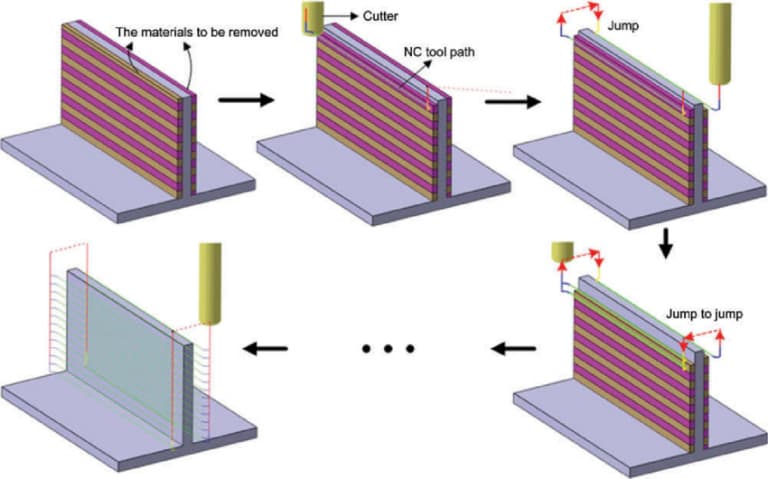
Crassi muri etiam productum pondus augebunt. Ergo excogitatores producti qui intendunt reducere pondus partium malle tendunt utentes parietibus tenuibus. Si autem muri crassitudo certum modum excedat, rigor erit gravis, et ad inflexionem ulterioris processus proclivis est.
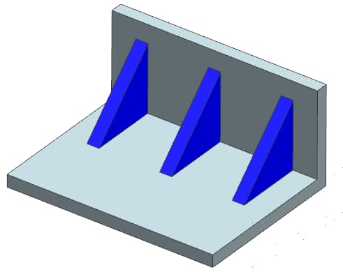
Quaestio inflexionis per processum sensim solvi potest. Sed tenues parietes fusurae rigore et viribus carent. costas roborare insertis rigiditatem parietum tenuium signanter augere possunt, easque firmiores efficiunt.
Tamen hodierni technologiae morientes technologiae iam provectae sunt satis ad tractandum maxime ambitum clavium designandi. Sed hae technologiae tantum considerari debent, si melius praestare poterunt exsecutionem vel utilitates oeconomicas pro partibus
PERFUSORIUS Design
Metallorum clientes et striati sunt duo notae communes designativae ponderis componentis. Signanter minuere possunt materiae quantitatem requisitam ad componentes fabricandi, integritatem et fortitudinem non afficientes.
Spatium salutiferum metallum significat ad spatia concava typice inventa intra costas roborandas, quae ad usum materialem reducere et per hoc pondus componentium minuere solent. Sectiones inter costas roborandas parum utiliter sunt et ideo a consilio tuto removeri possunt.
Design Suggestions for Metal Protectors
Cum protectores metalli ad partes designando, sequentia puncta prae oculis habere debent.
- Fuge acutas in metalli protectores. Utere angulis rotundatis/radii radio quam maximo. Radius minimus debet esse 0.06 inch (1.524mm).
- Muri uniformis crassitudine circa metallum protectorem conservandum. Stude ut crassitudo proximae pretii solitum commendetur.
- Praebere quantam undercut angulus quam maxime.
Loculos potest signanter reducere pondus
Sacculi similis structura est aliud pondus ars deminutio. Pars tenuis murata uti potest partem crassiorem foraminibus reponere, inde quantitatem materiae ad productionem requisitam reducere. Attamen sacculi-similis structura interdum irregularis deformitatis causat.
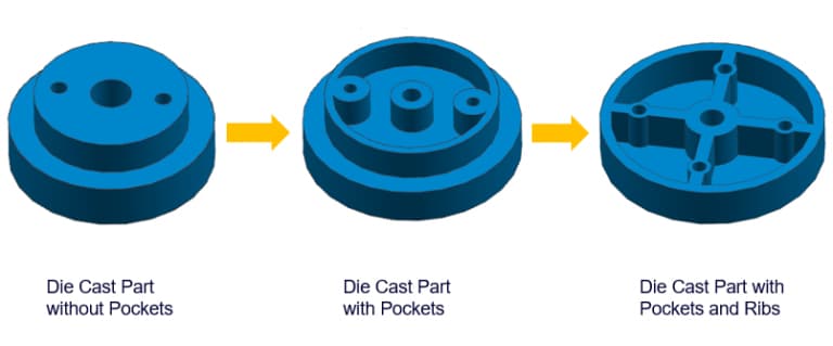
Ideo diligenter consideres ubi cavis utaris. Ad costas roborandas uti potes ad structuram cavitatum augendam. Hic cavitatum rigorem augebit et metalli fluxus emendavit. Reducendo quantitatem metallicae adhibitae, celeritatem refrigerationem augere etiam potest, ita ut cyclum productionem minuat.
Fillets & Radii
Although it is widely believed that rounded corners and radii are not the same thing, they are indeed different. While both refer to the rounded edges in the design of aluminum die-cast parts, the smooth inner angle is called a rounded corner, and the smooth outer edge is called a radius.
For any aluminum die-casting design, round corners and radii are extremely important features. They can significantly reduce the turbulence generated during the metal injection process, ensuring smoother metal flow. As a result, the parts can achieve better structural integrity.
Suggestion for Designing Infula/Radii
- Cum duae superficies secantes angulos acutos habent, rotundis angulis vel radiis utentes, eas coniungere possunt ne in ea parte formae vel componentis altam vim contrahere possint.
- Infula/Radii: Pro quibuslibet marginibus vel angulis in linea formse vitta, nulla vitta/radii requiruntur.
- Capturam angulum sufficientem praebent pro vittis, quae sunt perpendiculares ad lineam bipartitam.
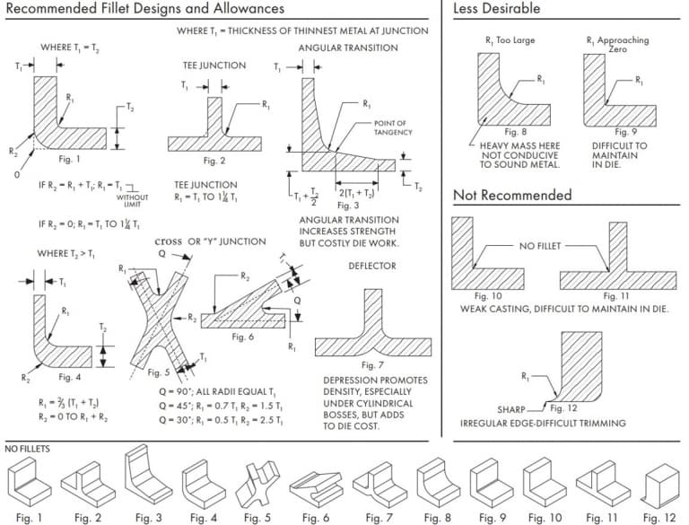
Infulam/radii in partibus secundum sequentes lineamenta designare potes
Shrinkage
Shrinkage is a very common and inevitable phenomenon. When any metal alloy is in the process of cooling and solidifying after being melted, there will be a certain degree of contraction. Therefore, designers must make necessary adjustments to the product design to leave space for shrinkage.
A thicker section is prone to shrinkage, which leads to the formation of pores inside. Local overheating can also cause shrinkage and subsequently result in pores. It is necessary to improve the mold design to locally cool these areas. However, this may increase the casting cycle.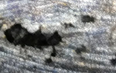
Artificia Reducing proicientes DECREMENTUM
Cogitatores hoc consilium sequi debent considerationes ad diminutionem aluminii dejectiones reducere.
- In consilio, sectiones superfluae vel crassae vitandae sunt. Si fieri potest, ratio recognoscenda debet uti sectionibus tenuioribus et nucleo materiae quae metallica salvantur.
- Additis costis planis vel verticalibus ad parietem notis pascendis emendare et inclinationem DECREMENTUM reducere.
- Compressio addit paxillos potest minuere DECREMENTUM in certis locis.
Boss
For the parts that need to be installed in other locations, the bosses are indispensable. They serve as support and installation points. However, if the design and positioning of the bosses are improper, it may lead to manufacturing difficulties and thus increase costs.
The bosses will also increase the material requirements and the weight of the aluminum castings. The protrusions can be redesigned in the following way to obtain lighter parts.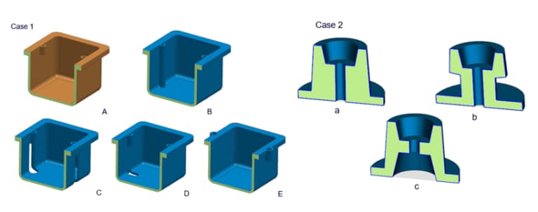
Design Considerations for Boss Design
The following are some design considerations that should be reason when designing the bullas in the parts.
- Si cavum exigitur, foveam addere conantur in centro suggesti elevati ad crassitudinem parietis uniformi perficiendam.
- Maiores autem angulis rotundatis exsertiones praebere, ut fusilis metallis convenienter influere sinat.
- Commendatur costas addere, prout possunt adiuvare ut bonam protrusionem repleant et insuper vires ad attributionem praebeant.
- Sufflationem protrusionem praebere, quo facilius ejici possint.
Hoc video breve est, quod applicationis et consilii processum explicatu suggestuum in mori iactu.
Ribs
The design of the reinforcing ribs is aimed at increasing the stiffness of the aluminum die-cast parts, thereby enhancing their strength. Therefore, the reinforcing ribs contribute to the robustness of the castings. They are usually used in combination with other weaker parts (such as thin-walled sections) to enhance their strength.
Its relatively thick solid cross-section typically provides higher strength because a thicker section usually has a higher porosity, thereby reducing its structural load-bearing capacity. However, excessive use of reinforcing ribs can lead to stress concentration at the edges of the reinforcing ribs.
The reinforcing ribs are usually designed with a hollow cross-section, also known as a metal-saving body. This approach can reduce the material usage of the reinforcing ribs, thereby reducing the weight of the parts.
The figure below shows the recommended rib sizes for some common scenarios and also indicates some situations where ribs should not be used.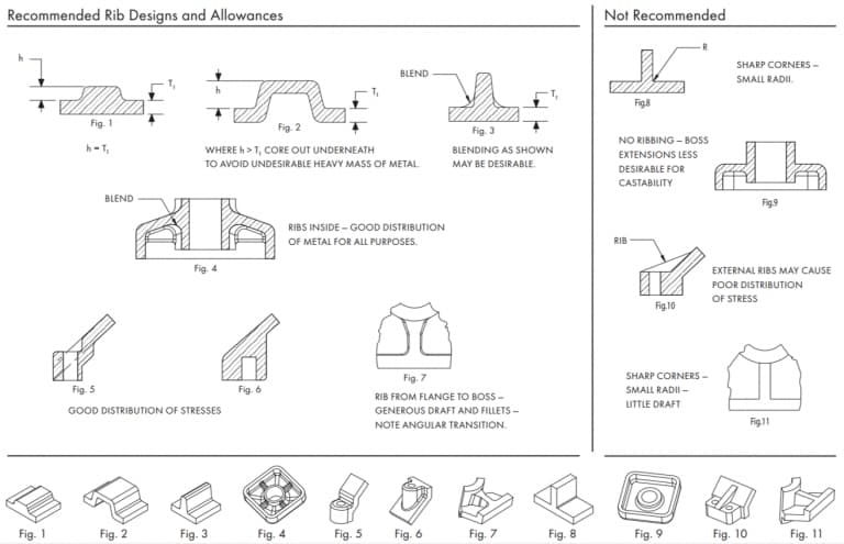
Hole to Edge Space Design
If the hole is too close to the edge of the aluminum casting, the cross-sectional strength will decrease. The minimum distance between the hole and the edge should be maintained to avoid excessive stress concentration in this area. Therefore, the appropriate distance between the hole and the edge should be determined based on the diameter of the hole. The minimum clear distance between two adjacent holes should also be maintained. For this purpose, the diameters of the two holes and their stress concentration areas should be considered.
The sufficient spacing is to avoid weak areas. If the distance between the hole and the edge is insufficient, secondary processing can also be considered.
Hole and Window
In terms of design difficulty, holes and windows are usually the easiest to handle. However, even the simplest features in aluminum die-cast parts require careful attention to details during the design process. During the design, it is necessary to ensure manufacturability.
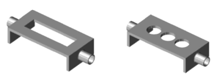 The most common applications of holes and windows are in the casings of various electronic devices, such as laptops and calculators. These devices require many holes to be placed. This layout causes problems for the flow of metal.
You can better understand this issue intuitively through this video.
Holes and windows can also make it difficult to remove the castings. This is because the solidification shrinkage of the parts can cause the castings to get stuck in the mold. When designing holes and windows, you can follow the following tips to solve these problems.
- Provide sufficient demolding capacity to solve the ejection problem. From the calculation of demolding capacity, you will notice that: holes and windows require a larger demolding capacity than any other structure. This is because flat and closed walls are set along the inner circumference.
- To prevent any problems during the metal flow process, you can use a bridge-like structure to ensure that the metal can flow continuously through the holes and windows. Providing lateral feed ports, burr and overflow ports can ensure smooth flow of the metal within the component. You can easily trim these additional structures later.
- If your design permits, you should remove the large window and replace it with a series of small holes. Because long windows can disrupt the metal flow and compromise the integrity of the casting.
Conantur vitare quam maxime
Designatores has lineas geometricae figere conentur parallelas formae eiectionis directionis, vel partem reddere ad tollendam necessitatem nuclei/slidi. Hoc exemplum ostendit quomodo partem resignare ad exigentiam nucleorum lateralium tollendam. 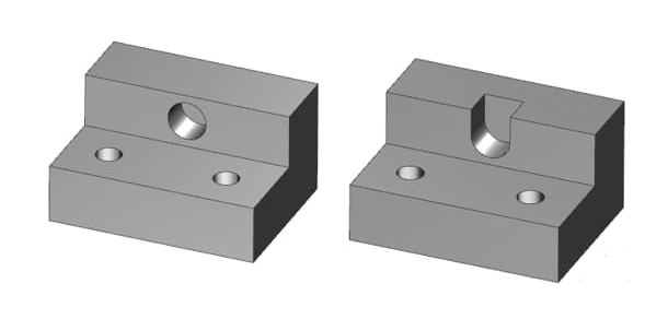
Tamen, in quibusdam casibus, coros/labitur debes mittere lineamenta sine necessitate processus sequentis. Potes designare nucleum labitur vel virgas trahere ad tollendam necessitatem maxime (si non omnes) operationum processus secundae.
Ideo difficultates ex moltis initialibus auctae sumptus et prolongata cycli dejectiones mitigari possunt reducendo numerum gradus processus secundarii. Quam ob rem, iteratio partium signanter emendata est.
Mechanismum opus
Cori-tractio lateralis mechanismi et motus lapsus plerumque ab inclinatis fibulis vel cylindricis hydraulicis acti sunt. Clavi inclinati sunt machinae mechanicae ad motum nucleum trahens/lapsus. Aperitio et conclusio sequentis formae principalis potest clavos inclinatos movere.
Unde fibulae inclinatae non possunt poni sine addito principio virtutis. Productio sumptus minor etiam est. Inclinatae autem fibulae possunt impedire discursum in flatura, et tantum aptae sunt ad breviores lapsus.
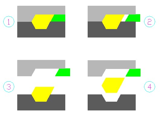
Summitas lapsus difficultatem etiam in clavibus articulis utens et fontes tantum uti potest. Methodus hydraulica utens has difficultates solvere potest. Potes cyclum definire et summo lapsus utere. Redivivus abjectiones impedit.
Aliae sunt modi motus qui pro core/ramo adhiberi possunt. Excogitator debet eligere convenientem motum methodum quae in factoribus fundatur, ut budget, volumen productionis, pars magnitudinis, et longitudo itineris core/arietis in dejectione.
Discutere potes officinam emissariis tuis ut opportunas suggestiones obtineas de consilio mechanismi lateris nuclei trahendi/lapsi. Interrogationes quoque tuas suscipimus et operam dabimus ut tibi subveniat.
Thread Forming
When we talk about thread forming, we mainly focus on casting external threads. Although internal threads can theoretically be cast, due to the complexity and cost of the manufacturing process, internal threads are not ideal.
The external thread can be easily manufactured by using a conventional aluminum die-casting device and properly aligning the parting line, or by using a simple slider mechanism. The internal thread, however, requires an assembly to rotate the core in the mold.
This will increase the cost of tools and parts. To enhance production speed and economy, internal threads are usually processed as a secondary operation. This way, there is no need to remove chips from the hole.
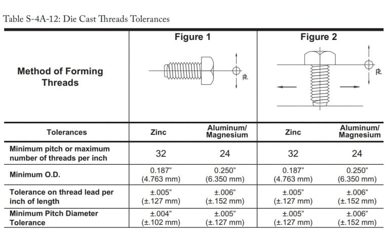
Idealis tolerances sequelarum
Stamina facile formari possunt per machinam aluminium iaciens. Stamina iactus plerumque ad stamina externa circumscripta quae non exigunt idoneum gradum accuratum.
Si certo gradu pro parte tua indigeas, officinam tuam moriendo semper consulere potes. Secundae processus Ad meliorem praecisionem perficiendam, accommodationes necessariae esse possunt. Praeterea maior diameter sequi debet definitionem stamina definitam ab utraque parte pactam.
Maximae et minimae tolerantiae aliquot ideales stamina operationum formantia sunt haec:
Post Design Considerationes
Nihilominus, cum fila creando, sequentia puncta prae oculis habe.
- Additae operationes torulo necessariae sunt ut siliquas inter stamina removenda sint.
- Conare directas tolerantias quam maxime applicare pro gradu filo definiendo.
- Hi valores tolerantiae limites includunt ad formas moventes componentes, lineas dividentes et dimensiones lineares.
- Cum tolerantiae filum durius exiguntur, quaeso officinam emissarium consule.
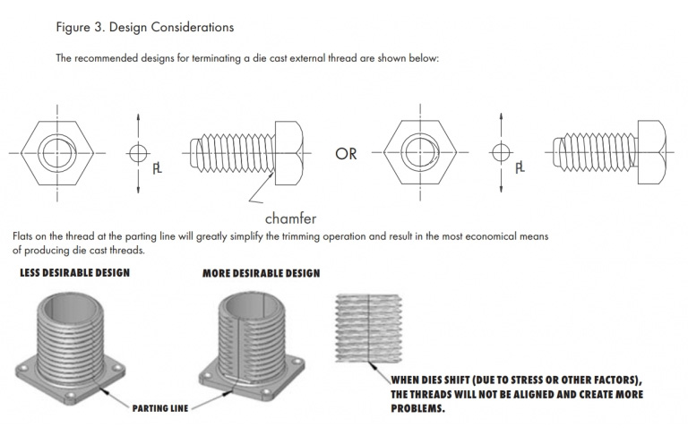
- Servans stamina in linea divortia levia signanter simpliciorem reddere processus fabricationis potest. Cum stamina plena-dia non sunt necessaria. Stamina glabra servans formam permittit ut leviter moveatur sine parte afficiens.
Sequens chart figuram filum externum commendatum ostendit.
Insert
The insert is a solid piece of material that is embedded in the mold and integrates with the aluminum die-cast part. When the selected alloy fails to meet the requirements and the design calls for integrating components made of other materials, inserts are needed.
There are professional systems that can be used in aluminum die casting to incorporate inserts. The inserts are placed within the mold cavity, and the molten aluminum flows around the inserts, thereby completing the die casting process.
When you encounter the following situations, you may need to incorporate threaded inserts in your design:
- The bearing points are prone to wear and tear.
- Due to the excessive frequent disassembly and insertion of fasteners, the threads will be overly worn.
- When you need threaded components with higher tensile strength to handle concentrated loads.
Insertion die casting is more costly than conventional casting, and the complexity of the insertion setup can also affect the production cost.
Proposita de insertione
- Distinxit omnes species quae requiruntur per mortem mittentes officinam esse. Ob magnum lacunam in forma, insertiones severiores tolerantias exigere solent. Placet impetrare approbationem officinas eiectationis morientis ad tolerantias insertorum sufficientes esse.
- Si emptoris laminas providere voluerit, quaeso cum officinas iectionibus tractandi sunt ut tolerantiae in acie cum suggestionibus officinas ejiciendi sint. Quia laminae cum tolerantia inconvenienter formae formam graviter laedunt.
- Accentus perscrutandi causa adiicit. Ut in ligula in felis tempor tempus non eu lacus.
- Insertio aliquo modo informari potest ut opus sit ut sufficientem ancorariam vim praebet ad condiciones onus expectatae.
- Vitare angulis acutis et aliis notis, quae possunt facere accentus concentration in partibus.
Undercut
The undercut usually refers to the concave geometric features or surfaces on a part that cannot be reached by a straight knife. In the die casting process, the undercut refers to the feature that restricts the casting from being ejected by a single pulling mechanism.
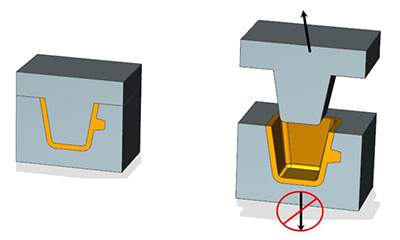
Therefore, when designing the parts, it is necessary to take into account the difficulties that may arise during the machining and casting processes. Sometimes, you can eliminate the effect of undercut by skillfully choosing the direction of aluminum die casting. However, in most cases, this cannot be achieved without introducing side cores.
Adding side cores to the design will make the mold structure and casting process more complex. Compared with the traditional aluminum die casting, the mechanism of side cores is more complicated, thus resulting in higher costs and requiring more time for setup.
When designing the undercut, it is essential to keep the following important points in mind.
- Discuss with your manufacturer whether it is possible to use specialized cutting tools that can reach hard-to-reach areas, such as T-shaped or V-shaped tools.
- Try to minimize the number of external cores. Because they require side cores, which will increase the cost of the mold.
- Adjusting the parting line can solve some undercut problems.
- Re-design your part to eliminate the internal undercut.
- Avoid undercutting that is not oriented towards the mold pulling direction. If side cores are not placed, they cannot be ejected.
- The undercutting below the boss will hinder the ejection of the aluminum casting.
However, if possible, it is best to avoid any kind of undercutting in the design.
Gutter Design
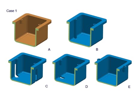
A slot is a narrow hole, and its end may have a rounded edge or may not. It mainly appears on flat rectangular aluminum parts. Its length is usually limited. The slot is always continuous, meaning it will completely penetrate the part.
Depending on the length and shape of the groove, there can be different types of grooves, such as length-bounded on both sides, length-bounded on one side, or a semi-circular elongated groove.
The grooves can be composed of various shapes and sizes, such as T-shaped grooves, dovetail grooves, rectangles, flat bottoms, V-shaped grooves, arcs, etc. They are usually cut along the edge and serve as features for installing components made of other materials.
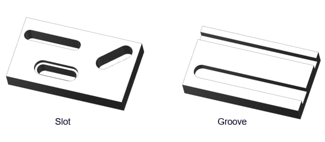
The slots and grooves in the design can serve as clamping elements for other components. They also provide openings through which other components (such as switches, levers, etc.) can pass.
When designing slots and grooves, the following tips might be helpful.
- Please remember that slots and grooves can hold or transfer the dimensions of other components.
- In the design, slots with too close spacing should be avoided. These slots will affect the integrity of the parts and cause problems during the finishing process.
- Do not leave any sharp edges in the rectangular/flat-bottomed groove. Try to round off all the inner and outer edges as much as possible. This will help minimize the electroplating cost and reduce minor problems.
- For the same reason, the angle of the V-shaped groove should also be circular.
Injector Design
Due to the solidification shrinkage, the solidified aluminum castings are prone to getting stuck in the mold. Therefore, some ejection components are needed to apply additional force from the inside of the mold to ensure that the castings can be ejected.
The ejection mechanism of the die-casting equipment can be composed of multiple components. The die-casting mold mainly consists of two parts, namely the cover mold half and the ejection mold half. The ejection mold contains the ejection mechanism.
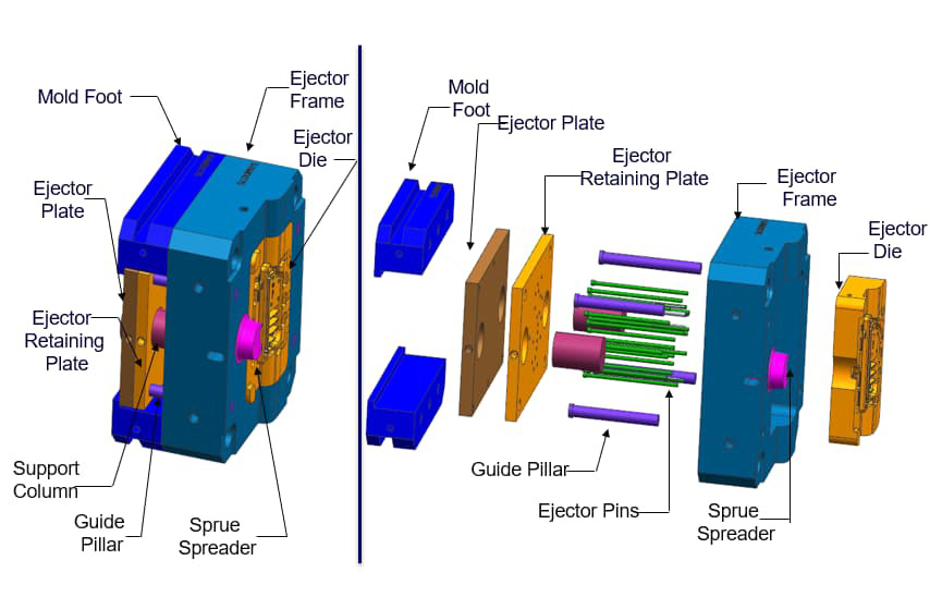
The parting line is the point where the two halves of the mold separate. After the casting is completed, the ejector mold separates from the parting line. However, due to the more complex equipment and multiple mold configurations, this makes the ejection system more complicated.
We will only discuss the traditional two-part molds, as these are more common and cost-effective. In this case, the ejection part of the mold includes pins, ejection plates, inserts, runners, and any engraved patterns present in the design.
The ejection mechanism mainly depends on two components of the mold: the ejection pin and the ejection plate.
Ejector Pin
Munus virgae impulsus est, ut solidatae formae ejectionem propelleret. Aliud munus virgae impulsus est fibulae iectionem impedire, ne ob vis contracta in solidificatione processum flectat. Sed incommodum est virga dis notas in jactu relinquet.
Itaque diligentius designandi locum et magnitudinem virgae dis positio et magnitudine, structura et aliis factoribus abiectionis fundatae sunt. Cum elaborandum est virga impulsum, secutae sunt lineae sequentes.
- Eiectorem clavum pone in area non-muneris proiectionis, ut fundum profundae cavitatis, portum redundantiam, attributionem vel costam imam.
- Cum fusuras tollens, virga ventilabis notas relinquet. Ergo, oro, non pone exteriorem superficiem dejectiones ad impulsum baculi.
- Commendata tolerantia ad notationem clavum oblongum vel reductum est 0.015" (0,381 mm).
- Quaeso consilium ut operariorum morientium mittentes, qui te adiuvare possunt in eligendo aptiorem magnitudinem, situm ac quantitatem fibularum fibularum.
Recta forma fabricandi modus signanter notas a dis virga relictas reducere potest. Sed hae notae adhuc clare conspicuae sunt. Instrumentum originale fabrica et morientes fabricare debet in institutione positio virgae impulsus consentire.
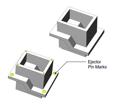
Etiam, quaeso, nota quod fimbrias circa summum acum formabunt. Lorem obiecta usitas nisi, fringilla non eveniet. Fimbriae summitates clavorum complanari possunt ad labefactum eorum extenuandum.
Ejector Plate
Lamina eiector potest esse componentis supplementi pro paxillus eiector vel independenter adhiberi potest. Fere officinas deiectionis utitur lamina eiector sicut superficies institutionis pro paxillus eiector. Cum pressio solum applicata laminae eiectori fuerit, eiector paxillus eodem tempore eiector clavum promovebit et eiectionem retractabit.
Catillus eiector etiam independenter operari potest sine clavo eiectoris necessitate. Sed solemus tantum in Micro-forma videre. Vim laminam eiectoris applicatam in partem eiciendi adhibetur. Commodum huius est quod lamina eiector non relinquit aliquas notas in mittente sicut paxillus eiector.
Sharp Edge
In the design of aluminum die castings, sharp edges should not be present. Sharp edges will create hotspots within the casting, and due to solidification shrinkage, these hotspots will cause stress concentration. This can lead to defects easily occurring at the corners. Moreover, it is also very difficult to apply coatings on sharp edges.
Therefore, designers tend to round off all the sharp corners, even if the radius is as small as possible. Apply rounded corners, radii or chamfers to all internal and external sharp corners. Here are some examples of sharp corner designs, and designers can redesign them in the following way.
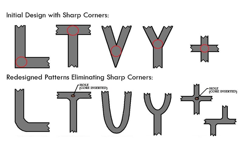
Another issue with the internal sharp edges is that they significantly increase the cost of the cutting tool. As is well known, the cost of mechanical processing is quite high, and the higher precision requirements will further increase the cost.
A perfectly sharp blade implies zero tolerance. Although an external blade can be achieved, the internal blade is almost impossible to reach such precision. Even with the most precise tools, the internal blade always has a minimum radius.
However, you can safely use sharp edges along the parting line to ensure that the two halves of the mold close completely. Besides, please try to minimize the use of sharp edges.
Pressure Sealing Property
Pressure sealing performance is an indicator for evaluating the integrity of aluminum die castings, indicating their ability to withstand a certain level of fluid pressure. In some cases, the purchaser may require the castings to have the specified pressure sealing performance.
The pressure sealing performance is largely determined by its density and porosity. Even a small amount of porosity can affect the pressure sealing performance of the component and may cause leakage during use. Various factors can influence the density and porosity of aluminum castings.
Air trapped inside the aluminum - this is a major concern for all manufacturers. When molten metal is injected under high pressure, the resistance caused by the trapped air can result in pores. The presence of air holes in the castings can also reduce their density, thereby compromising the structural integrity.
There are many factors contributing to the formation of pores, which makes it impossible for the castings to be completely pore-free. Effective DFM and good quality control throughout the production process will result in the appropriate density and the minimum porosity.
Factors Considered in Mold Design
Designers should take the following design parameters into account in order to achieve the best pressure sealing performance of aluminum die castings.
- Carefully follow the guidelines for round corners, reinforcing ribs and corner designs. Otherwise, the metal flow will not be smooth and turbulence may cause pores.
- Try to keep the wall thickness uniform to facilitate smooth metal flow. Avoid thick sections and any abrupt changes in thickness.
- For holes that require pressure sealing, the method of drilling should be used instead of mechanical processing to minimize the impact of porosity.
- All subsequent unprocessed holes and channels should be provided with sufficient draft angles. However, if the core holes are to be machined after casting, the minimum draft angle should be provided.
- Simulate the entire aluminum die-casting process to help you identify potential problems in advance. Run the mold flow analysis to determine which features of the mold can improve the quality of the castings.
- The vacuum-assisted die-casting equipment can significantly reduce the porosity of aluminum die-cast parts. As a result, there are fewer defects in the parts and better density performance.
Secondary Processing Operation
Secondary processing operations can also affect the pressure resistance of aluminum castings. The following guidelines should be followed during the processing.
- The most dense part of any casting is located on its surface or near it. The interior is usually less dense and has a higher porosity. Therefore, a minimum machining allowance should be specified to prevent the exposed porous parts in the interior of the casting.
- If the machining allowance required for the part exceeds the allowable limit, the internal porous parts may be exposed. Therefore, an additional impregnation treatment might be necessary to achieve the best sealing effect.
- Avoid processing the two sides of the castings that require pressure sealing.
- When processing a large number of blanks, it is advisable to avoid using a large draft angle. In particular, the minimum draft angle for the core hole should be taken into consideration.
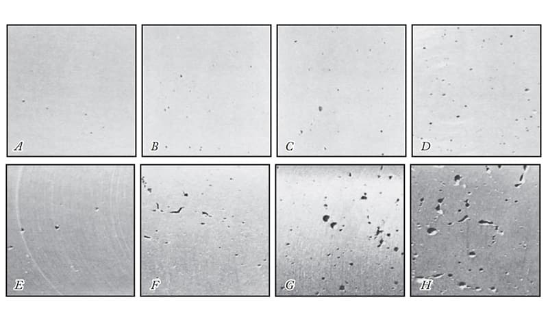
In addition to the aforementioned considerations, the selection of the alloy plays a crucial role in ensuring the pressure resistance of the aluminum castings. Certain alloys perform better in terms of the pressure resistance of aluminum components.
Various testing equipment can be used to measure the pressure resistance of aluminum parts. Usually, pressure resistance tests are conducted within a pressure range of 5 to 40 psi. If higher pressure resistance is required, the designer should consult with the die-casting factory.
Part Strength
The strength requirements for aluminum parts will have a significant impact on the overall production cost and time. Therefore, you can clearly discuss the strength requirements of the parts with the die casting factory to select a feasible aluminum die casting design method.
The strength of aluminum castings depends on many factors. Here we provide some tips on how to ensure the strength of castings.
- Firstly, an appropriate type of aluminum alloy needs to be selected. The alloy used for production has a significant impact on the strength of the parts. However, mechanical strength is not the only crucial parameter. The chosen alloy must have sufficient machinability and meet other requirements as well.
- It is best to cast as many features on-site as possible. Any features that are processed later will cause processing stress on the aluminum components.
- Using the vacuum-assisted aluminum die casting process to reduce the porosity of the parts. This will increase the density of the parts, thereby enhancing the structural integrity and strength.
- Adding reinforcing ribs to the thin-walled part and the platform will enhance its stability.
- Sharp edges are the hotspots of stress concentration. Therefore, these areas are prone to failure. You should use rounded corners to increase the rigidity of the part.
Following these guidelines can help you enhance the strength of the die-cast parts. However, you also need to consider many other details. Please discuss with your die-casting supplier and seek suggestions on how to increase the strength of the parts.
Minor Features
The processing of minute features requires more precise tools. The time, cost and difficulty of processing minute features are all higher. Features with standard tolerances can be achieved at a relatively lower cost and with sufficient accuracy to meet the needs of any ordinary consumer.
However, if your part is used in a very complex application, you may need precise tolerances. Processing beyond a certain level is called micro-processing, and standard processing tools cannot achieve this.
Micro-processing deals with machining features with tolerances far less than one millimeter. Compared to any standard machining operation, its cost is prohibitively high. Unless it is absolutely necessary, designers must avoid achieving such high precision in their designs.
If the mold develops defects prematurely, it will result in considerable maintenance costs. Therefore, efforts should be made to minimize minor defects in order to reduce the cost of the mold.
Die-Casting Engraving
Most aluminum castings will have some kind of text or decoration. These texts or decorations can be letters, logos, trademarks, date codes or production numbers, which are useful for tracking the supply chain, promoting the brand, and achieving many other purposes.
Die-casting engraving or decoration can be achieved on the parts in three ways.
- As an elevated feature
- As a characteristic of depression
- The raised letters on the concave panel
Among these three methods, the most economical one is to keep the letters as raised parts. The raised parts on the aluminum casting require the concave parts of the mold.
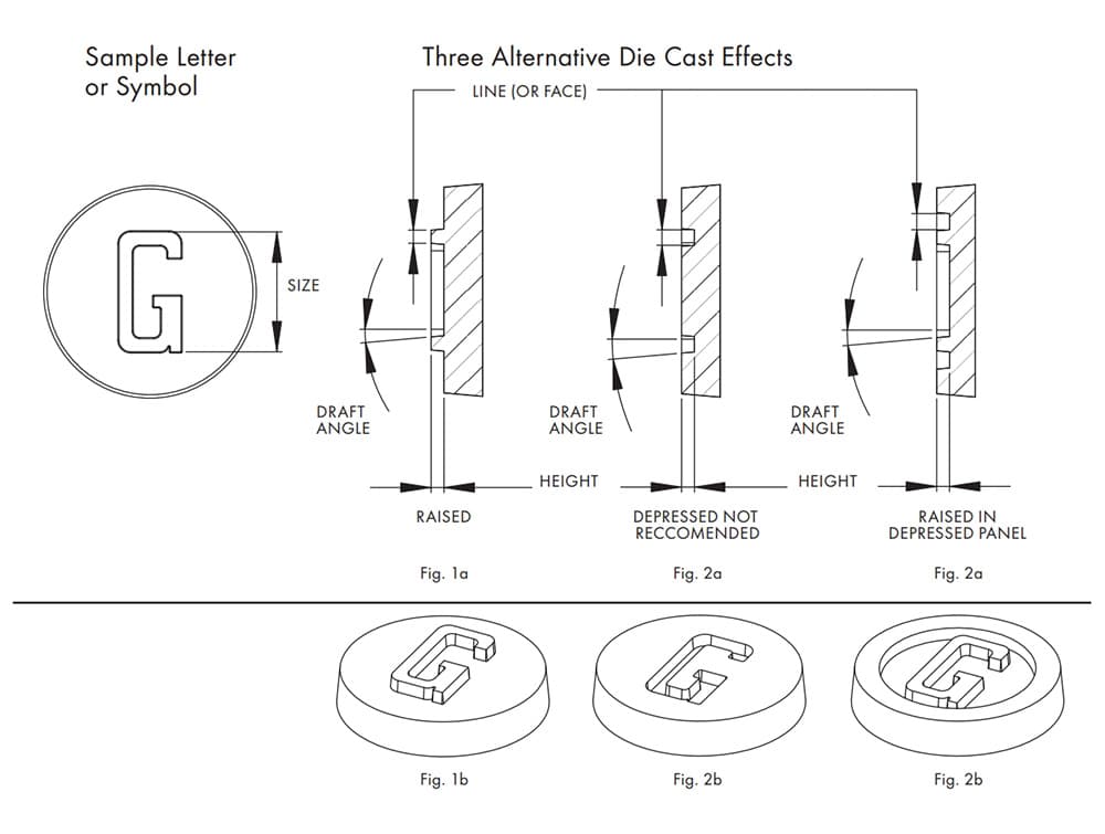
This feature is easy to be incorporated in the mold and causes minimal wear during operation. There are fewer raised (depressed) letters, and the construction cost of the mold as well as the maintenance cost throughout its entire service life are also lower.
On the contrary, the engraved characters on the aluminum castings require raised features, which will be raised into the mold steel. The construction is slightly more complex and the maintenance cost is also higher.
However, if the designer wishes to maintain a flat surface, then the text can be designed as a raised section within a recessed panel. This method is more practical as you can apply the recessed part without having to worry about damaging the mold.
Later, the coating can be used to fill in the additional recessed areas. Therefore, please avoid using recess features directly on the part.
Aliae rationes
- Superficies (lineae crassitudinis) cuiusvis litterae vel symboli debet esse saltem 0.010 pollicis (0.254 mm) vel maior.
- Altitudo linearum vel symbolorum debet esse aequalis vel minus quam linearum crassitudo.
- Si quis textus vel ornamentum singula vel subtilia litteratura implicata contineat, perspicuum esse non potest in processu dejectione. Qua re, studeas ea quam maxime simpliciorem reddere.
- Rectus haustus minus quam 10° esse debet.
Hae normae sequentes pro pluribus adiunctis utiles esse debent. Si alia requisita habes, semper potes officinam iectionis pro congruo consilio consulere.
QR code

Copyright © NINGBO CHIP MACHINERY CO., LTD. All Rights
ligula
 Custom Aluminium Alloy Die Proiciendi Manufacturers